Is your VCDS not communicating with your car, displaying a “No Response From Controller” error, or failing to connect during auto scans? CAR-CODING.EDU.VN understands the frustration this causes, especially when dealing with complex automotive coding and diagnostics. Our remote automotive coding support provides the expert assistance you need to overcome these challenges safely and efficiently. We provide solutions for ECU programming, hidden feature activation, and permanent fault code clearing.
Contents
- 1. Understanding the VCDS Communication Problem
- 1.1 What Does “No Response From Controller” Mean?
- 1.2 Common Scenarios Where VCDS Fails to Communicate
- 1.3 Importance of Proper Communication for Car Coding
- 2. Preliminary Checks for VCDS Communication Issues
- 2.1 Verifying the VCDS Interface Connection
- 2.2 Checking the Vehicle Battery Voltage
- 2.3 Confirming Ignition Status
- 3. Diagnosing Common Causes of VCDS Communication Failure
- 3.1 Addressing Aftermarket Radio Interference
- 3.2 Identifying and Resolving K-Line Issues
- 3.3 Examining CAN Bus Communication Problems
- 3.4 ECU Power Supply and Grounding Issues
- 3.5 Addressing Faulty Gateway Control Module
- 3.6 Investigating Issues with the OBDII Port
- 4. Advanced Troubleshooting Techniques
- 4.1 Using a Multimeter to Check for Continuity and Shorts
- 4.2 Testing the CAN Bus with an Oscilloscope
- 4.3 Checking ECU Grounds and Power Supplies
- 4.4 Performing a Component Test on Suspect Modules
- 5. Software and Firmware Troubleshooting
- 5.1 Updating VCDS Software and Firmware
- 5.2 Reinstalling VCDS Software
- 5.3 Ensuring Proper Driver Installation
- 6. Preventing Future Communication Problems
- 6.1 Maintaining a Stable Power Supply
- 6.2 Proper OBDII Port Care
- 6.3 Regularly Updating VCDS Software and Firmware
- 6.4 Secure Connections and Wiring Practices
- 7. Remote Automotive Coding Support from CAR-CODING.EDU.VN
- 7.1 How Remote Support Works
- 7.2 Benefits of Choosing CAR-CODING.EDU.VN
- 7.3 Specific Coding Services Offered
- 7.4 Ensuring Safe Coding Practices
- 8. Real-World Examples of Resolved VCDS Communication Issues
- 8.1 Case Study 1: Aftermarket Radio Interference on a VW Golf
- 8.2 Case Study 2: Faulty Gateway Control Module on an Audi A4
- 8.3 Case Study 3: Corroded OBDII Port on a BMW 3 Series
- 9. FAQ: Addressing Your VCDS Communication Concerns
- 9.1 Is it safe to perform car coding myself?
- 9.2 What is the process for remote coding support?
- 9.3 How much does remote coding support cost?
- 9.4 What types of vehicles and features do you support?
- 9.5 What equipment do I need for remote coding support?
- 9.6 What if something goes wrong during the coding process?
- 9.7 How long does remote coding support take?
- 9.8 What are the benefits of coding hidden features?
- 9.9 Can you help with clearing airbag lights permanently?
- 9.10 How do I get started with remote coding support?
- 10. Call to Action: Get Expert VCDS Support Now
1. Understanding the VCDS Communication Problem
When VCDS (VAG-COM Diagnostic System) fails to communicate with a car, it means your diagnostic tool cannot establish a reliable connection with the vehicle’s electronic control units (ECUs). This issue can manifest in several ways, such as the “K-Line Init Failed” error or a complete inability to perform auto scans. Communication failures can stem from various sources, ranging from simple connection problems to more complex ECU or wiring issues.
1.1 What Does “No Response From Controller” Mean?
The “No Response From Controller” error indicates that the VCDS software attempted to communicate with a specific ECU but did not receive any feedback. This can happen for several reasons:
- The controller is not powered up.
- The controller is faulty.
- There is a wiring issue preventing communication.
- The controller is not compatible with the VCDS software.
- There are issues with the diagnostic tool or its connection.
1.2 Common Scenarios Where VCDS Fails to Communicate
Here are a few common scenarios where VCDS might struggle to communicate with a car:
- Aftermarket Radio Installation: Incorrectly installed aftermarket radios can interfere with the K-line communication, preventing VCDS from accessing the ECUs.
- Faulty ABS Pump: Issues with the ABS pump or its control module can sometimes disrupt communication across the vehicle’s network.
- CAN Gateway Problems: The CAN gateway acts as a central communication hub, and any faults within it can lead to widespread communication failures.
- Wiring Issues: Damaged or corroded wiring, especially in the OBDII port or the CAN bus network, can prevent VCDS from connecting to the ECUs.
- ECU Malfunctions: A malfunctioning ECU may not respond to diagnostic requests, leading to communication errors.
- Software/Driver Issues: Outdated or corrupted software or drivers for the VCDS interface can cause connectivity problems.
- Incorrect VCDS Settings: Incorrect settings within the VCDS software, such as the wrong communication protocol, can also lead to connection failures.
- Low Battery Voltage: Insufficient battery voltage can prevent ECUs from powering up correctly, thus causing communication issues.
1.3 Importance of Proper Communication for Car Coding
Proper communication between the VCDS tool and the car’s ECUs is essential for effective car coding, programming, and diagnostics. Without a stable connection, you cannot:
- Read diagnostic trouble codes (DTCs).
- Clear fault codes permanently.
- Access and modify ECU settings.
- Activate hidden features.
- Perform adaptation and calibration procedures.
- Flash or update ECU software.
Effective car coding relies on accurate data transfer and modification, which is impossible without reliable communication. Any interruption can lead to incomplete procedures, data corruption, or even damage to the ECUs.
2. Preliminary Checks for VCDS Communication Issues
Before diving into more complex troubleshooting steps, perform these preliminary checks to rule out simple issues:
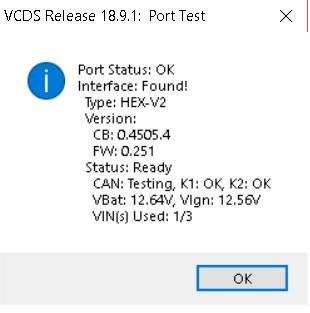
2.1 Verifying the VCDS Interface Connection
Ensure the VCDS interface is properly connected to both the car’s OBDII port and your computer. Here’s how:
- Check the OBDII Port: Ensure the OBDII port is clean and free from any obstructions.
- Secure Connection: Make sure the VCDS connector is firmly plugged into the OBDII port. A loose connection can cause intermittent communication.
- USB Connection: Verify that the USB cable connecting the VCDS interface to your computer is securely plugged in.
- Cable Condition: Inspect the cable for any signs of damage, such as cuts, fraying, or bent pins.
2.2 Checking the Vehicle Battery Voltage
Low battery voltage can prevent the ECUs from powering up correctly, leading to communication problems. Follow these steps to check the battery voltage:
- Multimeter Test: Use a multimeter to measure the battery voltage. A healthy battery should read around 12.6 volts when the engine is off.
- Load Test: Perform a load test to ensure the battery can maintain voltage under load.
- Charging the Battery: If the battery voltage is low, charge it fully and reattempt communication.
2.3 Confirming Ignition Status
The ignition must be switched on for most ECUs to be active and responsive to diagnostic requests. Here’s what to check:
- Ignition On: Ensure the ignition is switched to the “On” position (but do not start the engine).
- Dashboard Lights: Verify that the dashboard lights illuminate, indicating that the vehicle’s electrical system is powered up.
- ECU Power: Some vehicles require the engine to be running for certain ECUs to be accessible. Consult your vehicle’s service manual to confirm the correct procedure.
3. Diagnosing Common Causes of VCDS Communication Failure
If the preliminary checks don’t resolve the issue, investigate these common causes of VCDS communication failure:
3.1 Addressing Aftermarket Radio Interference
Aftermarket radios can sometimes interfere with the vehicle’s communication network, especially if they are not properly installed. Here’s how to troubleshoot:
- Disconnect the Radio: Disconnect the aftermarket radio to eliminate it as a potential source of interference.
- Test with OEM Radio: Reinstall the original OEM radio to see if communication is restored.
- Wiring Inspection: Check the radio wiring for any shorts, loose connections, or improper grounding.
- CAN Bus Compatibility: Ensure the aftermarket radio is CAN bus compatible and properly integrated with the vehicle’s electrical system.
3.2 Identifying and Resolving K-Line Issues
The K-line is a single-wire communication protocol used in older vehicles. Problems with the K-line can prevent VCDS from communicating with certain ECUs.
- Wiring Inspection: Inspect the K-line wiring for any breaks, shorts, or corrosion.
- Voltage Test: Use a multimeter to check the voltage on the K-line. Refer to the vehicle’s wiring diagram for the correct voltage specifications.
- Resistance Test: Measure the resistance of the K-line to identify any shorts or open circuits.
- K-Line Adapter: Some aftermarket devices require a K-line adapter to communicate properly with the vehicle.
3.3 Examining CAN Bus Communication Problems
The CAN (Controller Area Network) bus is a high-speed communication network used in modern vehicles. Problems with the CAN bus can cause widespread communication failures.
- CAN Bus Wiring: Check the CAN bus wiring for any damage, shorts, or open circuits.
- CAN Bus Voltage: Measure the voltage on the CAN high and CAN low wires. Refer to the vehicle’s wiring diagram for the correct voltage specifications.
- Termination Resistors: Verify that the CAN bus termination resistors are present and functioning correctly.
- Oscilloscope Testing: Use an oscilloscope to analyze the CAN bus signals and identify any anomalies.
3.4 ECU Power Supply and Grounding Issues
ECUs require a stable power supply and proper grounding to function correctly. Issues with the power supply or grounding can prevent the ECU from communicating with VCDS.
- Power Supply Voltage: Check the ECU’s power supply voltage with a multimeter. Ensure it is within the specified range.
- Grounding Points: Inspect the ECU’s grounding points for corrosion or loose connections.
- Wiring Diagrams: Refer to the vehicle’s wiring diagrams to identify the correct power and ground connections for the ECU.
3.5 Addressing Faulty Gateway Control Module
The gateway control module is responsible for managing communication between different networks within the vehicle. A faulty gateway module can disrupt communication and prevent VCDS from accessing the ECUs.
- Diagnostic Scan: Use VCDS to scan the gateway control module for any fault codes.
- Wiring Inspection: Check the gateway module’s wiring for any damage or loose connections.
- Module Replacement: If the gateway module is faulty, replace it with a new or tested used unit.
- Coding and Adaptation: After replacing the gateway module, you may need to perform coding and adaptation procedures using VCDS.
3.6 Investigating Issues with the OBDII Port
The OBDII (On-Board Diagnostics II) port is the gateway for communication between the diagnostic tool and the vehicle’s ECUs. Problems with the OBDII port can prevent VCDS from connecting to the car.
- Pin Inspection: Inspect the OBDII port pins for any damage, corrosion, or bent pins.
- Continuity Test: Use a multimeter to perform a continuity test on the OBDII port pins to ensure they are properly connected to the vehicle’s wiring harness.
- Voltage Test: Check the voltage on the OBDII port pins to ensure they are receiving power and ground.
- Wiring Diagrams: Refer to the vehicle’s wiring diagrams to identify the correct pin assignments for the OBDII port.
 OBDII Port
4. Advanced Troubleshooting Techniques
If the basic troubleshooting steps don’t resolve the communication issue, consider these advanced techniques:
4.1 Using a Multimeter to Check for Continuity and Shorts
A multimeter can be used to check for continuity and shorts in the vehicle’s wiring. This can help identify damaged or corroded wires that may be preventing communication.
- Continuity Test: Use the multimeter to check for continuity between different points in the wiring. A lack of continuity indicates a break in the wire.
- Short Test: Use the multimeter to check for shorts between the wiring and the vehicle’s chassis. A short can cause communication problems and damage to the ECUs.
- Wiring Diagrams: Refer to the vehicle’s wiring diagrams to identify the correct points to test for continuity and shorts.
4.2 Testing the CAN Bus with an Oscilloscope
An oscilloscope can be used to analyze the CAN bus signals and identify any anomalies. This can help diagnose problems with the CAN bus wiring, termination resistors, or ECUs.
- Signal Analysis: Use the oscilloscope to analyze the CAN high and CAN low signals. Look for any distortions, noise, or missing signals.
- Voltage Levels: Check the voltage levels of the CAN high and CAN low signals. Ensure they are within the specified range.
- Termination Resistors: Verify that the CAN bus termination resistors are functioning correctly by measuring the resistance between the CAN high and CAN low wires.
4.3 Checking ECU Grounds and Power Supplies
ECUs require a stable power supply and proper grounding to function correctly. Issues with the power supply or grounding can prevent the ECU from communicating with VCDS.
- Power Supply Voltage: Check the ECU’s power supply voltage with a multimeter. Ensure it is within the specified range.
- Grounding Points: Inspect the ECU’s grounding points for corrosion or loose connections.
- Wiring Diagrams: Refer to the vehicle’s wiring diagrams to identify the correct power and ground connections for the ECU.
4.4 Performing a Component Test on Suspect Modules
VCDS allows you to perform component tests on certain modules to verify their functionality. This can help identify faulty ECUs that may be causing communication problems.
- Module Selection: Select the suspect module in VCDS.
- Component Test: Choose the “Component Test” function.
- Test Execution: Follow the on-screen instructions to execute the component test.
- Results Analysis: Analyze the test results to determine if the module is functioning correctly.
5. Software and Firmware Troubleshooting
Sometimes, the issue isn’t with the car itself but with the VCDS software or the interface’s firmware.
5.1 Updating VCDS Software and Firmware
Outdated software or firmware can cause compatibility issues and communication problems. Follow these steps to update VCDS:
- Software Update: Download and install the latest version of the VCDS software from the Ross-Tech website.
- Firmware Update: Connect the VCDS interface to your computer and use the VCDS software to update the firmware.
- Driver Updates: Ensure that the drivers for the VCDS interface are up to date.
5.2 Reinstalling VCDS Software
If updating the software doesn’t resolve the issue, try reinstalling it:
- Uninstall VCDS: Uninstall the VCDS software from your computer.
- Download Latest Version: Download the latest version of the VCDS software from the Ross-Tech website.
- Reinstall VCDS: Reinstall the VCDS software on your computer.
- Driver Installation: Ensure that the drivers for the VCDS interface are properly installed.
5.3 Ensuring Proper Driver Installation
Incorrectly installed or outdated drivers can prevent the VCDS interface from communicating with your computer:
- Driver Verification: Check the Device Manager to ensure that the VCDS interface is recognized and that the drivers are properly installed.
- Driver Update: Update the drivers for the VCDS interface using the Device Manager or by downloading the latest drivers from the Ross-Tech website.
- Driver Reinstallation: If the drivers are corrupted, uninstall them and reinstall them using the Device Manager or by downloading the latest drivers from the Ross-Tech website.
6. Preventing Future Communication Problems
Taking proactive steps can help prevent future communication problems with your VCDS tool:
6.1 Maintaining a Stable Power Supply
A stable power supply is crucial for reliable communication. Use a battery maintainer or charger when performing coding or diagnostic procedures to prevent voltage drops.
6.2 Proper OBDII Port Care
Protect the OBDII port from damage and corrosion by keeping it clean and dry. Use a protective cover when the port is not in use.
6.3 Regularly Updating VCDS Software and Firmware
Keep your VCDS software and firmware up to date to ensure compatibility with the latest vehicle models and to benefit from bug fixes and performance improvements.
6.4 Secure Connections and Wiring Practices
Ensure that all connections are secure and that the wiring is in good condition. Inspect the wiring regularly for any signs of damage or corrosion.
7. Remote Automotive Coding Support from CAR-CODING.EDU.VN
When troubleshooting VCDS communication issues becomes too complex, CAR-CODING.EDU.VN offers remote automotive coding support to help you resolve the problem quickly and efficiently. Our experienced technicians can remotely diagnose and fix communication issues, ensuring that you can get back to coding and diagnostics without delay.
7.1 How Remote Support Works
Our remote support process is simple and straightforward:
- Contact Us: Reach out to CAR-CODING.EDU.VN via WhatsApp at +1 (641) 206-8880 or visit our website at CAR-CODING.EDU.VN.
- Initial Assessment: We’ll discuss your issue and gather information about your vehicle and VCDS setup.
- Remote Connection: Using secure remote access software, our technician will connect to your computer.
- Diagnosis and Repair: We’ll diagnose the communication problem and perform the necessary steps to resolve it.
- Verification: We’ll verify that the communication issue is resolved and that you can successfully use VCDS to code and diagnose your vehicle.
7.2 Benefits of Choosing CAR-CODING.EDU.VN
- Expertise: Our technicians have extensive experience with VCDS and automotive coding.
- Remote Convenience: Get help from the comfort of your own garage or workshop.
- Time Savings: Resolve communication issues quickly and efficiently, minimizing downtime.
- Cost-Effectiveness: Avoid the expense of taking your vehicle to a dealership or specialist.
- Safety: Ensure that coding and diagnostic procedures are performed safely and correctly.
7.3 Specific Coding Services Offered
CAR-CODING.EDU.VN offers a wide range of coding services, including:
- ECU Programming: We provide ECU programming services to update or modify the software in your vehicle’s control units.
- Hidden Feature Activation: We can activate hidden features in your vehicle, such as cornering lights, coming/leaving home lights, and more.
- Fault Code Clearing: We can clear fault codes permanently, ensuring that your vehicle is running smoothly.
- Adaptation and Calibration: We can perform adaptation and calibration procedures to ensure that your vehicle’s components are functioning correctly.
Here’s an example of features that can be coded on different car models:
| Car Model | Available Coding Features |
|---|---|
| Audi A4/A5 | Enable cornering lights, activate coming/leaving home lights, adjust daytime running lights (DRL), enable lap timer, enable gauge staging |
| Volkswagen Golf/GTI | Enable soundaktor adjustment, activate tear wiping, enable Scandinavian DRL, enable auto-dimming mirror dip on reverse, personalize drive mode |
| BMW 3/5 Series | Enable folding mirrors with key fob, disable seatbelt chime, enable video in motion (VIM), customize ambient lighting |
7.4 Ensuring Safe Coding Practices
CAR-CODING.EDU.VN prioritizes safety in all coding procedures. Our technicians follow industry best practices and take precautions to prevent damage to your vehicle’s ECUs. We also provide guidance on how to perform coding safely and correctly.
Safety Measures:
- Backup ECU Data: Always back up the ECU data before performing any coding or programming procedures.
- Stable Power Supply: Ensure a stable power supply to prevent voltage drops during coding.
- Correct Coding Parameters: Use the correct coding parameters for your vehicle model and year.
- Verify Coding Results: Verify the coding results after each procedure to ensure that the changes have been applied correctly.
8. Real-World Examples of Resolved VCDS Communication Issues
Here are a few examples of how CAR-CODING.EDU.VN has helped customers resolve VCDS communication issues:
8.1 Case Study 1: Aftermarket Radio Interference on a VW Golf
A customer with a VW Golf was experiencing communication problems with VCDS after installing an aftermarket radio. Our technician remotely diagnosed the issue and determined that the radio was interfering with the CAN bus. By disconnecting the radio and reconfiguring the CAN bus settings, we were able to restore communication and allow the customer to perform coding procedures.
8.2 Case Study 2: Faulty Gateway Control Module on an Audi A4
A customer with an Audi A4 was unable to communicate with any of the vehicle’s ECUs. Our technician remotely diagnosed the issue and determined that the gateway control module was faulty. After the customer replaced the gateway module, we remotely coded and adapted the new module, restoring full communication and functionality.
8.3 Case Study 3: Corroded OBDII Port on a BMW 3 Series
A customer with a BMW 3 Series was experiencing intermittent communication problems with VCDS. Our technician remotely diagnosed the issue and determined that the OBDII port was corroded. After the customer cleaned the OBDII port and applied dielectric grease, we were able to establish a stable connection and allow the customer to perform coding procedures.
9. FAQ: Addressing Your VCDS Communication Concerns
Here are some frequently asked questions about VCDS communication issues:
9.1 Is it safe to perform car coding myself?
Yes, if you follow proper procedures and take necessary precautions. Always back up your ECU data before making any changes.
9.2 What is the process for remote coding support?
You contact us, we assess your needs, connect remotely to your computer, perform the coding, and verify the results.
9.3 How much does remote coding support cost?
The cost varies depending on the complexity of the coding procedure. Contact us for a quote.
9.4 What types of vehicles and features do you support?
We support a wide range of vehicles and features. Contact us to see if we can assist with your specific needs.
9.5 What equipment do I need for remote coding support?
You need a VCDS interface, a laptop with internet access, and the VCDS software installed.
9.6 What if something goes wrong during the coding process?
We have safety measures in place to prevent issues, and we can restore your ECU to its original state if necessary.
9.7 How long does remote coding support take?
The duration varies depending on the complexity of the coding procedure. Most procedures can be completed in under an hour.
9.8 What are the benefits of coding hidden features?
Coding hidden features can enhance your driving experience and add convenience and functionality to your vehicle.
9.9 Can you help with clearing airbag lights permanently?
Yes, we can help with clearing airbag lights and other fault codes permanently.
9.10 How do I get started with remote coding support?
Contact us via WhatsApp at +1 (641) 206-8880 or visit our website at CAR-CODING.EDU.VN to schedule a remote coding session. Our office is located at 100 Tech Innovation Dr, Suite 500, San Jose, CA 95110, United States.
10. Call to Action: Get Expert VCDS Support Now
Are you struggling with VCDS communication issues or need assistance with car coding? Don’t waste time and risk damaging your vehicle’s ECUs. Contact CAR-CODING.EDU.VN today for expert remote automotive coding support. Our experienced technicians are ready to help you resolve communication problems, activate hidden features, clear fault codes, and more.
- Contact Us: WhatsApp: +1 (641) 206-8880
- Website: CAR-CODING.EDU.VN
- Office: 100 Tech Innovation Dr, Suite 500, San Jose, CA 95110, United States
Let CAR-CODING.EDU.VN be your trusted partner for all your car coding needs!