Is your VCDS showing “No Response from Controller” in Windows 10? Yes, a “No Response from Controller” error in VCDS on Windows 10 can be frustrating, especially when trying to perform essential tasks like releasing the Electronic Parking Brake (EPB). CAR-CODING.EDU.VN offers expert remote support to diagnose and resolve VCDS connection issues, ensuring safe and efficient car coding and ECU programming. This comprehensive guide provides troubleshooting steps and explains how our remote assistance services can help you overcome this problem.
Contents
- 1. Understanding the “No Response from Controller” Error in VCDS
- 1.1 Why Does This Error Occur?
- 1.2 Identifying the Affected Control Module
- 2. Initial Troubleshooting Steps for VCDS “No Response”
- 2.1 Verify VCDS Cable Connection
- 2.2 Confirm Ignition Status
- 2.3 Test the VCDS Cable
- 2.4 Check Battery Voltage
- 2.5 Restart VCDS and Your Computer
- 3. Advanced Troubleshooting for VCDS “No Response”
- 3.1 Update or Reinstall USB Drivers
- 3.2 Check VCDS Configuration Settings
- 3.3 Disable Antivirus and Firewall
- 3.4 Run VCDS as Administrator
- 3.5 Windows 10 Compatibility Mode
- 3.6 Check Vehicle Wiring and Fuses
- 3.7 Review Autoscan for Clues
- 4. The Role of CAN Bus in VCDS Communication
- 4.1 Understanding CAN Bus Communication
- 4.2 Common CAN Bus Problems
- 4.3 Diagnosing CAN Bus Issues
- 5. Addressing the Specific Errors in the Autoscan
- 6. When to Seek Expert Remote Support from CAR-CODING.EDU.VN
- 6.1 Benefits of Our Remote Support Services
- 6.2 How Our Remote Support Works
- 7. Specific VCDS Coding and Programming Services We Offer
- 7.1 Example: Releasing EPB for Brake Service
- 8. Essential Equipment for VCDS Coding and Programming
- 9. Safety Precautions When Using VCDS
- 10. Understanding Coding, Programming, Flashing, and Activating Hidden Features
- 10.1 Coding
- 10.2 Programming
- 10.3 Flashing
- 10.4 Activating Hidden Features
- 11. Examples of VCDS Coding Applications by Vehicle Model
- 12. Potential Risks of Incorrect Coding
- 13. Communication Protocols Used in Modern Vehicles
- 14. How to Obtain a Complete and Accurate Autoscan
- 15. Addressing Power-Related Issues and Voltage Drops
- 15.1 Identifying Voltage Drops
- 15.2 Common Causes of Voltage Drops
- 15.3 Solutions for Voltage Drops
- 15.4 Importance of a Stable Power Supply
- 16. The Importance of Following VCDS Procedures and Documentation
- 16.1 Understanding VCDS Procedures
- 16.2 Accessing and Utilizing VCDS Documentation
- 16.3 Key Elements of VCDS Procedures and Documentation
- 16.4 Consequences of Not Following VCDS Procedures
- 16.5 Best Practices for Following VCDS Procedures
- 17. Understanding and Troubleshooting U-Codes (Communication Faults)
- 17.1 Common Causes of U-Codes
- 17.2 Diagnosing U-Codes
- 17.3 Troubleshooting Steps for U-Codes
- 17.4 Specific U-Codes in the Provided Autoscan
- 18. Ensuring VCDS Software and Firmware are Up-to-Date
- 18.1 Benefits of Updating VCDS Software and Firmware
- 18.2 How to Update VCDS Software
- 18.3 How to Update VCDS Interface Firmware
1. Understanding the “No Response from Controller” Error in VCDS
The “No Response from Controller” error in VCDS (VAG-COM Diagnostic System) indicates a communication problem between the VCDS software running on your Windows 10 computer and the vehicle’s control module (ECU). This prevents you from accessing and modifying the module’s settings. It’s one of the most prevalent issues technicians encounter when using VCDS for car coding and diagnostics.
1.1 Why Does This Error Occur?
Several factors can cause the VCDS “No Response from Controller” error:
- Incorrect VCDS Configuration: VCDS may not be properly configured to communicate with the vehicle’s specific protocol (e.g., K-line, CAN bus, UDS).
- Faulty Interface Cable: A damaged or incompatible VCDS interface cable can disrupt communication.
- Driver Issues: Outdated, corrupted, or missing USB drivers for the VCDS interface cable.
- Windows 10 Compatibility Issues: VCDS software version is not fully compatible with the Windows 10 operating system, leading to communication conflicts.
- Vehicle-Specific Issues: Problems with the vehicle’s wiring, a faulty control module, or a discharged battery.
- Ignition Status: The vehicle’s ignition may not be in the correct position (usually “ON” but engine off).
- Software Conflicts: Other software running on your Windows 10 system might interfere with VCDS communication.
1.2 Identifying the Affected Control Module
The error message usually specifies which control module is not responding. In the provided autoscan, several modules show a “Malfunction” status, including:
- 05-Acc/Start Auth.
- 08-Auto HVAC
- 09-Cent. Elect.
- 13-Auto Dist. Reg
- 17-Instruments
- 36-Seat Mem. Drvr
- 5F-Information Electr.
This widespread communication issue suggests a potential problem with the VCDS setup or the vehicle’s communication network rather than individual module failures.
2. Initial Troubleshooting Steps for VCDS “No Response”
Before seeking expert help, try these basic troubleshooting steps:
2.1 Verify VCDS Cable Connection
- Check the Connection: Ensure the VCDS cable is securely plugged into both the vehicle’s OBD-II port and your computer’s USB port.
- Try a Different USB Port: Sometimes, a specific USB port may have issues. Test with different USB ports on your computer.
2.2 Confirm Ignition Status
The vehicle’s ignition must be switched ON (but the engine should be OFF) for VCDS to communicate with the control modules. Some modules might require the engine to be running. Refer to the VCDS documentation or the specific procedure you’re trying to perform.
2.3 Test the VCDS Cable
- VCDS Cable Test: In the VCDS software, go to “Options” and click the “Test” button under “Select Interface.” This will diagnose the cable’s functionality and communication with your computer.
- Check Cable Status: The test will indicate whether the cable is recognized and functioning correctly. If the test fails, the cable might be faulty or the drivers might be improperly installed.
2.4 Check Battery Voltage
Low battery voltage can interfere with ECU communication. Ensure the vehicle’s battery is adequately charged (at least 12.5V). Using a battery charger during coding or diagnostic procedures is highly recommended to maintain a stable voltage supply.
2.5 Restart VCDS and Your Computer
A simple restart of the VCDS software and your Windows 10 computer can resolve temporary glitches that might be causing communication issues.
3. Advanced Troubleshooting for VCDS “No Response”
If the basic steps don’t work, try these advanced troubleshooting techniques:
3.1 Update or Reinstall USB Drivers
- Device Manager: Open Device Manager in Windows 10.
- Locate VCDS Interface: Find the VCDS interface cable (usually listed under “Ports (COM & LPT)” or “USB Serial Devices”).
- Update Driver: Right-click on the device and select “Update driver.” Choose “Search automatically for updated driver software.”
- Reinstall Driver: If updating doesn’t work, uninstall the device, disconnect the cable, restart your computer, and then reconnect the cable. Windows should automatically reinstall the driver. If not, manually install the drivers from the Ross-Tech website.
3.2 Check VCDS Configuration Settings
- Access Options: In VCDS, go to “Options.”
- Interface Selection: Ensure the correct interface type is selected (usually “USB”).
- COM Port Settings: If using a COM port interface, verify the correct COM port is selected.
- Protocol Settings: Ensure the appropriate communication protocol is selected for your vehicle (VCDS usually auto-detects this, but manual configuration might be necessary in some cases).
3.3 Disable Antivirus and Firewall
Antivirus software or firewalls can sometimes block VCDS communication. Temporarily disable them to see if it resolves the issue. Remember to re-enable them after troubleshooting.
3.4 Run VCDS as Administrator
Running VCDS with administrator privileges can resolve permission-related issues. Right-click on the VCDS shortcut and select “Run as administrator.”
3.5 Windows 10 Compatibility Mode
- Locate VCDS Executable: Find the VCDS executable file (usually in
C:Ross-TechVCDS). - Compatibility Settings: Right-click on the executable file, select “Properties,” and go to the “Compatibility” tab.
- Run in Compatibility Mode: Check the box “Run this program in compatibility mode for” and select an older version of Windows (e.g., Windows 7 or Windows XP).
- Apply Changes: Click “Apply” and then “OK.”
3.6 Check Vehicle Wiring and Fuses
Inspect the vehicle’s wiring and fuses related to the affected control module. A blown fuse or damaged wire can prevent communication with the module. Consult the vehicle’s wiring diagrams for fuse and wiring locations.
3.7 Review Autoscan for Clues
Analyze the complete autoscan report for any other error codes or communication issues that might be related to the “No Response” error. The autoscan provided shows several communication faults (U-codes), which suggest a potential issue with the CAN bus or the gateway module.
4. The Role of CAN Bus in VCDS Communication
The CAN (Controller Area Network) bus is a critical communication network within the vehicle. It allows various control modules to exchange data. Problems with the CAN bus can lead to widespread communication issues, including the “No Response from Controller” error.
4.1 Understanding CAN Bus Communication
The CAN bus uses a two-wire system (CAN High and CAN Low) to transmit data between ECUs. Each ECU has a CAN transceiver that sends and receives messages on the bus.
4.2 Common CAN Bus Problems
- Wiring Issues: Damaged, shorted, or open CAN bus wires.
- Termination Resistors: Incorrect or missing termination resistors (usually 120 ohms) at each end of the CAN bus.
- ECU Faults: A faulty ECU can disrupt CAN bus communication.
- CAN Gateway Problems: The CAN gateway module is responsible for managing communication between different CAN buses in the vehicle. A faulty gateway can cause widespread communication issues.
4.3 Diagnosing CAN Bus Issues
- Visual Inspection: Inspect the CAN bus wiring for any signs of damage.
- Continuity Testing: Use a multimeter to check the continuity of the CAN High and CAN Low wires.
- Resistance Measurement: Measure the resistance between the CAN High and CAN Low wires with the ignition off. It should be approximately 60 ohms (two 120-ohm resistors in parallel).
- Oscilloscope Testing: Use an oscilloscope to analyze the CAN bus signal waveform. This can help identify signal distortions or communication errors.
5. Addressing the Specific Errors in the Autoscan
The provided autoscan reveals several error codes that need to be addressed:
-
Address 05: Acc/Start Auth. (J518):
14222592 - Databus U1121 00 [008] - Missing Message [Message ELV_01 missing]
This error indicates a missing message related to the Electronic Steering Lock (ELV). It could be due to a faulty ELV module, wiring issues, or a CAN bus communication problem.
-
Address 08: Auto HVAC (E87):
263425 - Air Quality Sensor B10AF 04 [008] - Internal System Fault
This error indicates an internal fault with the air quality sensor. It might require replacing the sensor or checking its wiring.
-
Address 09: Cent. Elect. (J519):
204290 - Remote key 1 B1479 18 [009] - Current Too Low204546 - Remote key 2 B147A 18 [009] - Current Too Low
These errors indicate a problem with the remote key fobs, possibly due to low battery voltage or faulty key fobs.
-
Address 13: Auto Dist. Reg (J428):
0836 - Databus U1123 00 [008] - Received Error Message [FAULT_PREDICTIVE_ROUTEDATA_SIGNALERROR_RECEIVED]196741 - Sensor for Automatic Distance Control C110B F0 [008] - Limited Visibility [FCTSEN_BLOCKAGE]196742 - Sensor for Automatic Distance Control C110B F0 [008] - Limited Visibility [FCTSEN_DEC_BLOCKAGE]196743 - Sensor for Automatic Distance Control C110B F0 [008] - Limited Visibility [FCTSEN_INC_BLOCKAGE]
These errors suggest issues with the Automatic Distance Control (ACC) system, possibly due to a blocked sensor or communication problems.
-
Address 17: Instruments (J285):
16777020 - Function Restricted due to Interrupted Communications U1110 00 [008] - - [BAP_TEL_0x28 keine Kommunikation]
This error indicates a communication problem with the infotainment system or telephone module.
-
Address 36: Seat Mem. Drvr (J810):
13893632 - Function Restricted due to Insufficient Voltage U1400 00 [008] - - [Funktionseinschränkung durch Unterspannung --> funktionelle Einschränkungen aufgrund vorübergehender Unterspannung in der Versorgung.]
This error indicates low voltage to the seat memory module.
Alt: VCDS interface cable connected to a car’s OBD-II port and a laptop’s USB port, showing the physical connection for car diagnostics.
6. When to Seek Expert Remote Support from CAR-CODING.EDU.VN
If you’ve exhausted the troubleshooting steps above and are still facing the “No Response from Controller” error, it’s time to seek expert help from CAR-CODING.EDU.VN. Our experienced technicians can remotely diagnose and resolve complex VCDS issues, saving you time and frustration.
6.1 Benefits of Our Remote Support Services
- Expert Diagnosis: Our technicians have extensive knowledge of VCDS and vehicle communication systems. We can quickly identify the root cause of the “No Response” error.
- Remote Assistance: We can remotely access your computer and VCDS software to perform diagnostics and coding procedures.
- Safe and Secure: We use secure remote access tools to protect your data and vehicle.
- Cost-Effective: Remote support is often more affordable than taking your vehicle to a dealership or specialist.
- Convenient: Get expert help from the comfort of your home or workshop.
- Wide Range of Vehicle Support: We support a wide range of Volkswagen, Audi, Skoda, and SEAT vehicles.
6.2 How Our Remote Support Works
-
Contact Us: Reach out to CAR-CODING.EDU.VN via WhatsApp at +1 (641) 206-8880 or visit our website at CAR-CODING.EDU.VN to request remote support.
-
Provide Details: Provide us with details about your vehicle (make, model, year), the VCDS error you’re experiencing, and any troubleshooting steps you’ve already tried.
-
Schedule a Session: We’ll schedule a remote support session at a time that’s convenient for you.
-
Remote Access: We’ll use secure remote access software (e.g., TeamViewer) to connect to your computer.
-
Diagnosis and Resolution: Our technician will diagnose the problem and guide you through the necessary steps to resolve the “No Response from Controller” error. This might involve:
- Verifying VCDS configuration settings
- Updating or reinstalling USB drivers
- Analyzing the autoscan report
- Performing advanced diagnostics on the vehicle’s communication network
- Coding or programming control modules as needed
-
Testing and Verification: We’ll test the connection to the control modules to ensure the issue is resolved.
7. Specific VCDS Coding and Programming Services We Offer
CAR-CODING.EDU.VN offers a comprehensive range of VCDS coding and programming services, including:
- Activating Hidden Features: Enable features that are present in your vehicle but not activated by default (e.g., cornering lights, coming home/leaving home lights, disabling seatbelt warnings).
- ECU Programming: Update or modify the software in your vehicle’s ECUs to improve performance, fuel efficiency, or add new functionality.
- Clearing Fault Codes: Permanently clear fault codes and warning lights.
- Adaptations: Perform adaptations to adjust the behavior of various systems (e.g., throttle response, steering assist).
- Retrofitting: Code and configure new hardware components (e.g., new headlights, parking sensors) after installation.
- Variant Coding: Modify the vehicle’s configuration to match specific equipment levels or regional requirements.
7.1 Example: Releasing EPB for Brake Service
The original poster’s goal was to release the Electronic Parking Brake (EPB) to access the rear brake pads and rotors. This procedure typically involves the following steps:
- Connect VCDS: Connect the VCDS cable to the vehicle’s OBD-II port and your computer.
- Select Control Module 53 (Parking Brake): In VCDS, select control module 53 (Parking Brake).
- Basic Settings: Go to “Basic Settings.”
- Release Parking Brake: Select the “Release Parking Brake” function.
- Follow Instructions: Follow the on-screen instructions to complete the procedure.
If you’re encountering the “No Response from Controller” error when trying to access module 53, our remote support team can help you diagnose the problem and perform the EPB release procedure remotely.
8. Essential Equipment for VCDS Coding and Programming
To perform VCDS coding and programming effectively, you’ll need the following equipment:
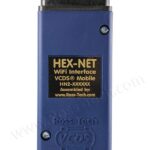
- VCDS Interface Cable: A genuine Ross-Tech VCDS interface cable (HEX-V2 or newer).
- Windows 10 Laptop: A Windows 10 laptop with a stable internet connection.
- Battery Charger: A battery charger to maintain a stable voltage supply during coding.
- OBD-II Extension Cable (Optional): An OBD-II extension cable can make it easier to connect to the vehicle’s OBD-II port.
Alt: Ross-Tech HEX-V2 VCDS interface cable, a diagnostic tool used for car coding and ECU programming.
9. Safety Precautions When Using VCDS
- Use Genuine Equipment: Always use a genuine Ross-Tech VCDS interface cable. Clones or counterfeit cables can damage your vehicle’s ECUs.
- Follow Instructions Carefully: Carefully follow the instructions in the VCDS documentation and any instructions provided by our remote support team.
- Backup Your Data: Before making any changes to your vehicle’s coding, create a backup of the original coding. This allows you to revert to the original settings if something goes wrong.
- Maintain Stable Voltage: Ensure the vehicle’s battery voltage is stable during coding. Use a battery charger if necessary.
- Avoid Interruptions: Do not interrupt the coding process. Avoid turning off the ignition or disconnecting the VCDS cable while coding is in progress.
- Seek Expert Help: If you’re unsure about any coding procedure, seek expert help from CAR-CODING.EDU.VN.
10. Understanding Coding, Programming, Flashing, and Activating Hidden Features
10.1 Coding
Coding involves modifying software parameters within an ECU to enable or disable specific features or adjust system behavior. It’s like changing settings in a program to customize how it works. Coding is often used to activate hidden features or adapt systems to different equipment levels.
Example: Changing the coding in the Central Electronics module to enable cornering lights.
10.2 Programming
Programming (also known as flashing) involves replacing the entire software in an ECU with a new version. This is typically done to update the ECU with the latest software fixes, improve performance, or add new functionality. Programming is a more complex process than coding and requires special tools and knowledge.
Example: Updating the engine control unit (ECU) with a new software version to improve fuel efficiency.
10.3 Flashing
Flashing is another term for programming, referring to the process of writing new software to an ECU’s memory.
10.4 Activating Hidden Features
Many modern vehicles have features that are built into the car but not activated by default. These are often referred to as “hidden features.” VCDS coding can be used to activate these features, unlocking new functionality without requiring any hardware modifications.
Examples of Hidden Features:
| Feature | Description |
|---|---|
| Cornering Lights | Activates fog lights to illuminate the direction of turn at low speeds. |
| Coming Home/Leaving Home Lights | Turns on headlights or fog lights when unlocking or locking the vehicle in dark conditions. |
| Needle Sweep | Sweeps the instrument cluster needles upon startup. |
| Lane Assist Sensitivity | Adjusts the sensitivity of the lane-keeping assist system. |
| Traffic Sign Recognition | Enables the display of traffic signs on the instrument cluster or navigation system (if the vehicle has the necessary hardware). |
| Off-Road Display | Displays off-road information such as steering angle, compass, and altitude on the infotainment screen (if the vehicle has the necessary hardware). |
11. Examples of VCDS Coding Applications by Vehicle Model
| Vehicle Model | Common VCDS Coding Applications |
|---|---|
| VW Golf | Activating cornering lights, needle sweep, disabling seatbelt warning, adjusting throttle response. |
| Audi A4 | Enabling traffic sign recognition, activating high beam assist, customizing ambient lighting. |
| Skoda Octavia | Activating rain closing, enabling tear wiping, customizing daytime running lights. |
| SEAT Leon | Enabling hill hold assist, activating auto-dimming mirrors, adjusting the sensitivity of the parking sensors. |
| VW Tiguan | Activating off-road display, enabling trailer assist, customizing the behavior of the adaptive cruise control. |
| Audi Q5 | Activating lane assist, enabling blind spot monitoring, customizing the display of the virtual cockpit. |
12. Potential Risks of Incorrect Coding
Incorrect coding can lead to various problems, including:
- Malfunctioning Systems: Incorrect coding can cause systems to malfunction or stop working altogether.
- Warning Lights: Incorrect coding can trigger warning lights on the instrument cluster.
- ECU Damage: In rare cases, incorrect coding can damage the vehicle’s ECUs.
- Voided Warranty: Incorrect coding can void the vehicle’s warranty.
To mitigate these risks, it’s essential to:
- Use Genuine Equipment: Use a genuine Ross-Tech VCDS interface cable.
- Follow Instructions Carefully: Carefully follow the instructions in the VCDS documentation.
- Backup Your Data: Create a backup of the original coding before making any changes.
- Seek Expert Help: If you’re unsure about any coding procedure, seek expert help from CAR-CODING.EDU.VN.
13. Communication Protocols Used in Modern Vehicles
Modern vehicles use various communication protocols to enable ECUs to exchange data. Understanding these protocols is essential for diagnosing and resolving communication issues.
- CAN (Controller Area Network): The most common communication protocol in modern vehicles. It’s used for communication between engine control units, transmission control units, ABS modules, and other systems.
- K-Line: An older single-wire communication protocol used in older vehicles.
- MOST (Media Oriented Systems Transport): A high-speed communication protocol used for multimedia systems, such as infotainment systems and audio amplifiers.
- FlexRay: A high-speed, fault-tolerant communication protocol used in advanced systems, such as adaptive cruise control and active suspension.
- DoIP (Diagnostics over Internet Protocol): A communication protocol used for diagnostics and programming over Ethernet.
The provided autoscan shows that the vehicle uses CAN bus for communication, as indicated by the numerous U-codes related to communication faults.
14. How to Obtain a Complete and Accurate Autoscan
A complete and accurate autoscan is essential for diagnosing VCDS issues. Here’s how to obtain one:
- Connect VCDS: Connect the VCDS cable to the vehicle’s OBD-II port and your computer.
- Start VCDS: Start the VCDS software.
- Select Vehicle: Select your vehicle’s make, model, and year.
- Run Autoscan: Click the “Autoscan” button.
- Wait for Completion: Wait for the autoscan to complete. This can take several minutes.
- Save the Autoscan: Save the autoscan report to a file.
- Provide the Complete Report: When seeking help, provide the complete autoscan report, including all control modules and error codes.
15. Addressing Power-Related Issues and Voltage Drops
Voltage drops and power-related issues can significantly impact VCDS communication and coding processes. Modern vehicles are highly sensitive to voltage fluctuations, and even slight deviations from the optimal voltage range can cause communication errors, ECU malfunctions, and coding failures. Here’s how to identify and address power-related problems:
15.1 Identifying Voltage Drops
- Monitor Battery Voltage: Use a multimeter to monitor the vehicle’s battery voltage before, during, and after VCDS operations. Ideally, the voltage should remain stable within the range of 12.5V to 13.5V.
- Check VCDS Readings: VCDS itself often displays the battery voltage. Monitor this value during coding or diagnostics.
- Look for Low Voltage Error Codes: Many ECUs generate specific error codes related to low voltage. These codes can provide valuable clues about power-related issues. In the provided autoscan, the error code in Address 36 (Seat Mem. Drvr) indicates a function restriction due to insufficient voltage.
15.2 Common Causes of Voltage Drops
- Weak Battery: A weak or aging battery is the most common cause of voltage drops. Have the battery tested and replaced if necessary.
- Excessive Load: Running multiple electrical devices simultaneously (e.g., headlights, air conditioning, radio) can put a strain on the battery and cause voltage drops.
- Faulty Alternator: A faulty alternator might not be able to adequately charge the battery, leading to voltage drops during VCDS operations.
- Poor Ground Connections: Poor or corroded ground connections can increase resistance in the electrical system and cause voltage drops.
- Wiring Issues: Damaged or corroded wiring can also contribute to voltage drops.
15.3 Solutions for Voltage Drops
- Use a Battery Charger/Maintainer: Connect a high-quality battery charger/maintainer to the vehicle’s battery during VCDS operations. This will help maintain a stable voltage and prevent voltage drops.
- Turn Off Accessories: Turn off unnecessary electrical accessories (e.g., headlights, air conditioning, radio) to reduce the load on the battery.
- Check and Clean Ground Connections: Inspect all ground connections for corrosion or looseness. Clean and tighten them as needed.
- Test the Alternator: Have the alternator tested to ensure it’s functioning properly.
- Repair Wiring Issues: Repair any damaged or corroded wiring in the vehicle’s electrical system.
- Replace Weak Battery: If the battery is weak or aging, replace it with a new one.
15.4 Importance of a Stable Power Supply
Maintaining a stable power supply is crucial for the success and safety of VCDS coding and programming. Voltage drops can interrupt the coding process, leading to incomplete or corrupted data being written to the ECUs. This can cause various problems, including malfunctioning systems, warning lights, and even ECU damage.
By addressing power-related issues and ensuring a stable power supply, you can minimize the risk of coding errors and protect your vehicle’s electronic systems.
16. The Importance of Following VCDS Procedures and Documentation
Accurate VCDS coding relies heavily on adhering to established procedures and documentation. Straying from the recommended guidelines can lead to unforeseen issues, system malfunctions, or even potential damage to the vehicle’s electronic control units (ECUs). Here’s why it’s crucial to follow VCDS procedures and documentation meticulously:
16.1 Understanding VCDS Procedures
VCDS procedures are step-by-step guides that outline the correct way to perform specific coding, programming, or diagnostic tasks. These procedures are developed by Ross-Tech and automotive experts who have a deep understanding of vehicle systems and VCDS capabilities.
16.2 Accessing and Utilizing VCDS Documentation
- Ross-Tech Wiki: The Ross-Tech Wiki is a comprehensive online resource that provides detailed information on VCDS procedures, coding guidelines, and troubleshooting tips. It’s an invaluable tool for VCDS users of all skill levels.
- VCDS Software Help Files: The VCDS software itself includes built-in help files that provide context-sensitive information on various functions and features.
- Vehicle-Specific Forums and Communities: Online forums and communities dedicated to specific vehicle makes and models can offer valuable insights and guidance on VCDS coding. However, it’s important to verify the accuracy of information from these sources before implementing it.
16.3 Key Elements of VCDS Procedures and Documentation
- Prerequisites: VCDS procedures typically list the prerequisites for the task, such as the required VCDS version, interface cable, vehicle condition (e.g., ignition on, engine off), and any other necessary tools or equipment.
- Step-by-Step Instructions: VCDS procedures provide detailed, step-by-step instructions on how to perform the task. These instructions should be followed carefully and precisely.
- Coding Values and Adaptations: VCDS procedures often specify the correct coding values or adaptations that need to be entered to achieve the desired outcome. It’s crucial to enter these values correctly, as even slight errors can have unintended consequences.
- Safety Precautions: VCDS procedures often include safety precautions to ensure the task is performed safely and without risk of damage to the vehicle or injury to the user.
- Troubleshooting Tips: VCDS procedures may also include troubleshooting tips to help resolve common issues that may arise during the task.
16.4 Consequences of Not Following VCDS Procedures
- System Malfunctions: Deviating from VCDS procedures can cause systems to malfunction or stop working altogether.
- Warning Lights: Incorrect coding can trigger warning lights on the instrument cluster.
- ECU Damage: In rare cases, incorrect coding can damage the vehicle’s ECUs.
- Voided Warranty: Incorrect coding can void the vehicle’s warranty.
16.5 Best Practices for Following VCDS Procedures
- Read the Procedure Carefully: Before starting any VCDS task, read the procedure carefully and ensure you understand all the steps involved.
- Gather All Necessary Tools and Equipment: Gather all the necessary tools and equipment before starting the task.
- Follow the Instructions Precisely: Follow the instructions precisely, without skipping any steps or deviating from the recommended guidelines.
- Double-Check Coding Values: Double-check all coding values before entering them into VCDS.
- Create a Backup: Create a backup of the original coding before making any changes.
- Seek Expert Help: If you’re unsure about any coding procedure, seek expert help from CAR-CODING.EDU.VN.
17. Understanding and Troubleshooting U-Codes (Communication Faults)
U-codes, also known as communication fault codes, indicate problems with communication between different electronic control units (ECUs) within the vehicle. These codes are typically stored in the gateway module or other ECUs that monitor communication on the CAN bus or other communication networks. In the provided autoscan, several U-codes are present, indicating potential communication issues.
17.1 Common Causes of U-Codes
- Wiring Issues: Damaged, shorted, or open CAN bus wires or other communication wires.
- ECU Faults: A faulty ECU can disrupt communication on the network.
- CAN Gateway Problems: The CAN gateway module is responsible for managing communication between different CAN buses in the vehicle. A faulty gateway can cause widespread communication issues.
- Software Incompatibilities: Incompatibilities between the software versions in different ECUs can cause communication problems.
- Network Overload: Excessive traffic on the communication network can lead to dropped messages and U-codes.
- Power Supply Issues: Voltage drops or power supply problems can interfere with ECU communication.
17.2 Diagnosing U-Codes
- Identify the Affected ECUs: Determine which ECUs are involved in the communication fault. The U-code will typically indicate which ECUs are experiencing communication problems.
- Inspect Wiring: Inspect the wiring between the affected ECUs for any signs of damage, corrosion, or loose connections.
- Check CAN Bus Resistance: Measure the resistance between the CAN High and CAN Low wires with the ignition off. It should be approximately 60 ohms (two 120-ohm resistors in parallel).
- Test ECU Functionality: Test the functionality of the affected ECUs to ensure they are working properly.
- Check Software Versions: Verify that the software versions in the affected ECUs are compatible.
- Monitor Network Traffic: Use a diagnostic tool to monitor the traffic on the communication network. This can help identify network overloads or other communication problems.
17.3 Troubleshooting Steps for U-Codes
- Clear the U-Codes: Use VCDS to clear the U-codes and see if they return.
- Inspect Wiring and Connections: Inspect the wiring and connections between the affected ECUs for any signs of damage, corrosion, or loose connections. Repair or replace any damaged wiring or connections.
- Check CAN Bus Resistance: Measure the resistance between the CAN High and CAN Low wires with the ignition off. If the resistance is not approximately 60 ohms, troubleshoot the CAN bus wiring and termination resistors.
- Test ECU Functionality: Test the functionality of the affected ECUs to ensure they are working properly. Replace any faulty ECUs.
- Update Software Versions: Update the software versions in the affected ECUs to ensure they are compatible.
- Address Power Supply Issues: Address any power supply issues that may be interfering with ECU communication.
17.4 Specific U-Codes in the Provided Autoscan
The provided autoscan includes the following U-codes:
- Address 05: Acc/Start Auth. (J518):
14222592 - Databus U1121 00 [008] - Missing Message [Message ELV_01 missing]
- Address 13: Auto Dist. Reg (J428):
0836 - Databus U1123 00 [008] - Received Error Message [FAULT_PREDICTIVE_ROUTEDATA_SIGNALERROR_RECEIVED]
- Address 17: Instruments (J285):
16777020 - Function Restricted due to Interrupted Communications U1110 00 [008] - - [BAP_TEL_0x28 keine Kommunikation]
These U-codes indicate communication problems with the Electronic Steering Lock (ELV), Automatic Distance Control (ACC), and the infotainment system or telephone module. Troubleshooting these U-codes will likely involve inspecting the wiring, testing the functionality of the affected ECUs, and verifying software compatibility.
18. Ensuring VCDS Software and Firmware are Up-to-Date
Keeping your VCDS software and interface firmware up-to-date is crucial for optimal performance, compatibility, and access to the latest features and bug fixes. Outdated software or firmware can lead to communication issues, coding errors, and compatibility problems with newer vehicle models.
18.1 Benefits of Updating VCDS Software and Firmware
- Improved Compatibility: Updates ensure compatibility with the latest vehicle models and control modules.
- Bug Fixes: Updates address known bugs and issues in the software, improving stability and reliability.
- New Features: Updates often introduce new features and functionality, expanding the capabilities of VCDS.
- Enhanced Performance: Updates can improve the performance and speed of VCDS operations.
- Access to Latest Data: Updates provide access to the latest data files and coding information.
18.2 How to Update VCDS Software
- Check for Updates: Start the VCDS software and check for updates. The software will typically notify you if an update is available.
- Download the Update: Download the latest version of the VCDS software from the Ross-Tech website.
- Install the Update: Follow the instructions to install the update.
- Run VCDS: Start VCDS to ensure the update was installed successfully.
18.3 How to Update VCDS Interface Firmware
- Connect VCDS Interface: Connect the VCDS interface cable to your computer.
- Start VCDS: Start the VCDS software.
- Check Firmware Version: Go to “Options” and click the “Test” button under “Select Interface.” The test will display the current firmware version of the interface cable.
- Update Firmware: If a firmware update is available, VCDS will prompt you to update the firmware. Follow the on-screen instructions to update the firmware.
- Wait for Completion: Wait for the firmware update to complete. Do not interrupt the update process